

Setting AVR Fuse Bits: How to change fuse bits of AVR Atmega328p / Atmega8 / Atmega16 / Atmega32
We all know about how AVR ATmega32A chip is clocked. In all our previous lessons we have used 1 MHz internal clock to drive AVR chip. This is default clock setting with which ATmega chip been shipped from factory. Here in this lesson we’ll learn setting AVR Fuse Bits to use different clock speed for various applications. It’s important where we require very accurate and precise timing say for example to implement serial UART, USB Communication. We have fuse bit’s in AVR Microcontrollers. We can use these fuse bits to clock microcontroller with desired frequency.
Let’s first understand the basic concept and ideas associated with setting up an clock source (either internal or external clock). I highly recommend opening up datasheet of ATmega32A (or any your microcontroller) for the duration of this tutorial, and briefly skimming the chapter on system clock and clock option (Page 25) click here for ATmega32A datasheet.
What are AVR Fuse Bits?
As we all knows the AVR microcontroller have in general, three memory areas: FLASH, which is dedicated to program code, SRAM for run-time variable and EEPROM, which can be used by user code to store data that have to be preserved when MCU is turned OFF. Now the lock/fuses together form a fourth memory area available for programming. This holds a few bytes for fuses: Low Byte, High Byte.
Before we begin to analyze fuse and lock bits. We have to keep in mind that a bit set to ‘0’ means programmed and a bit set to ‘1’ means un-programmed. This is little bit tricky and very important to be noted before we proceed any further.
In this tutorial we want to show, how you can clock your microcontroller with different frequency (setting avr fuse bits). Typically, there are only two fuse bytes: a high one and low one. We’ll be focusing more on its usage. The practical example in this tutorial will allow you to understand concept thoroughly and you’ll be ready to experiment further by your own. We’ll cover Lock bits in future lesson. The location of specific fuse bits differs among all the fuse bytes depending on AVR chip used. SO be sure to write them down before setting them. As example we take ATmega32A microcontroller and here are all fuse bytes for it.
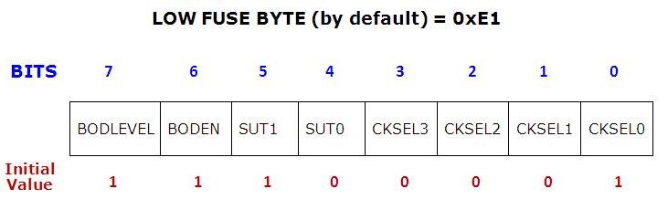
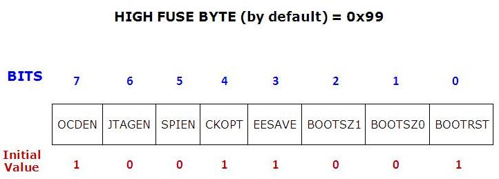
The default value of ATmega32/32A fuse bit is 0x99E1 i.e. high fuse: 0x99 and low fuse: 0xE1 with this default setting frequency is set to 1 MHz, Internal RC oscillator, startup time:6CK+64ms:
avr fuse bits tutorial,how to set fuse bits in atmega16,atmega16 fuse bits external crystal,avrdude set fuses,arduino fuse settings,avrdude read fuses,atmega328p 16mhz fuse settings,atmega lock bits,AVR Tutorial - Fuses - Ladyada.net,Setting AVR Fuse Bits - BINARYUPDATES,AVR fuse bits settings - Embedded Electronics Blog,[TUT][SOFT] Recovering from a "locked out" AVR | AVR Freaks,Crash-Bang Prototyping | How to Use AVR Fuses,Fuses and Lock Bits - Oregon State EECS,AVR fuse bits explained | Hackaday,AVR Fuse Bits | zembedded,How to change fuse bits of AVR Atmega328p - 8bit microcontroller,Howto recover wrong fuses settings on a AVR | Jkx@home,
Disclaimer: This tutorial is for informational purpose; do fuse bits settings at your own risk.
Explanation of Each Fuse Bit:
BODLEVEL: The trigger level of BOD (Brown-out Detection) can be selected by this fuse bit. When programmed (0) the trigger level is 4V and when not programmed (1) the trigger level is 2.7V
BODEN: ATmega32A has on chip brown-out detection (BOD) circuit for monitoring the VCC level during operation by comparing it to fixed trigger level. When the BOD is enabled (BODEN programmed), and VCC decreases to a value below the trigger level, the Brown-out reset is immediately activated. When VCC increases above the trigger level, it starts the microcontroller again.
SUT1:0: These bits select a startup time. The default value of SUT1:0 results in maximum startup time (6CK & 65ms additional delay from RESET [Ref. Table:8-9, Page No: 30].
CLKSEL [3-0]: These bits used to select different clock options available. The default value of CLKSEL[3..0] is 0001 i.e. internal RC oscillator running at 1 MHz If you want to add external crystal then you need to change value according to [Table 8-1, Page No:26]. Some common fuse bits value given in the end of this article.
OCDEN: This pin is used to enable or disable on chip debugging. This allows a real time emulation of microcontroller when running in target system. By default it is disable as ‘1’ means not programmed.
JTAGEN: There is built in JTAG interfaces for debugging. It is enabled in new microcontroller. This is reason why some newbie say, “PORTC of ATmega32 not working as expected “ disable it if you are not using JTAG by making JTAGEN bit 1 (high).
SPIEN: 0 value (programmed) means serial programming of ATmega32/32A enabled. Don’t change this unless you have parallel programmer! Because once disabled ATmega32A can’t be programmed using serial programmer.
CKOPT: The CKOPT fuse selects between two different oscillator amplifier modes. When CKOPT is programmed, the oscillator output will oscillate with a full rail-to-rail swing on the output. When not programmed, the oscillator has a smaller output swing. If you’re using external oscillator, it is better to program CKOPT i.e. CKOPT = 0
EESAVE: If programmed (0) it will save EEPROM from erasing during chip erase else EEPROM would also be erased with flash.
BOOTSZ0 and BOOTSZ1: These bits are used to set the size of bootloader
BOOTRST: If BOOTRST bit is programmed (0), The device will jump on first address bootloader block.
Example: Setting AVR Fuse Bits
At this point you’re ready to clock your microcontroller with different frequencies. In this example, we’ll be generating beep using Piezo disc. And impact will be shown in terms of change in beeps. Let’s calculate fuse bits, for different clock frequency. Here is a wonderful program to calculate fuse bits for you AVR Fuse Calculator

Clock selection
The first option is how the chip is clocked. Every CPU uses a clock, The clock keeps track of time for the chip, in general one assembly code instruction is run every clock cycle.The one in your PC has a clock that runs at 1GHz or higher. This little chip runs much slower. If you look at the menu you'll see a huge list of options, but looking carefully you'll see there are two groupings, the Clock Source, the Clock Startup
The Clock Source can be either of the following:
External Clock, Internal 8MHz clock, Internal 4MHz clock, Internal 128KHz clock, External Crystal (0.4-0.9 MHz), External Crystal (0.9MHz - 3.0MHz), External Crystal (3.0MHz - 8.0MHz) or External Crystal (8.0MHz +)
External Clock, Internal 8MHz clock, Internal 4MHz clock, Internal 128KHz clock, External Crystal (0.4-0.9 MHz), External Crystal (0.9MHz - 3.0MHz), External Crystal (3.0MHz - 8.0MHz) or External Crystal (8.0MHz +)
The Clock Startup can be either of the following:
14CK + 0 ms, 14CK + 4 ms, 14CK + 65 ms.
14CK + 0 ms, 14CK + 4 ms, 14CK + 65 ms.
External Clock means that a square wave is being input into the CLOCK-IN pin. This is pretty rare unless you have a clock generating chip. Don't use this unless you're sure you mean to
Internal Clock means that theres a little oscillator inside the chip, its not very precise but good for most projects that dont have fine timing issues. The clock varies with temperature and the power supply voltage. You can chose from a 8MHz, 4MHz or 128KHz clock. The 128KHz clock is for very low power applications where running the chip very slowly helps conserve power. Having an internal oscillator means we don't need to wire up a crystal and we can use the clock pins for our own nefarious purposes.
External Crystal
If you need a special clock rate, like 3.58MHz or 12MHz or a high precision clock that won't drift with the temperature, you'll want an external crystal or oscillator.
Case 1: 1 MHz Internal Clock (default), Low Fuse: 0xE1 High Fuse: 0x99
Case 2: 8 MHz Internal Clock, LowFuse: 0xE4 High Fuse: 0x99
Case 3: 16 MHz External Crystal, Low Fuse: 0xFF High Fuse: 0x99
Tags:
um technologies, um
technologies, um technologies, um technologies, um technologies, um
technologies, uzair mushtaq, uzair mushtaq, uzair mushtaq, uzair mushtaq, uzair
mushtaq, uzair mushtaq, uzair mushtaq,avr fuse bits tutorial,how to set fuse
bits in atmega16,atmega16 fuse bits external crystal,avrdude set
fuses,arduino fuse settings,avrdude read fuses,atmega328p 16mhz fuse settings,atmega
lock bits,AVR Tutorial - Fuses - Ladyada.net,Setting AVR Fuse Bits -
BINARYUPDATES,AVR fuse bits settings - Embedded Electronics Blog,[TUT][SOFT]
Recovering from a "locked out" AVR | AVR Freaks,Crash-Bang
Prototyping | How to Use AVR Fuses,Fuses and Lock Bits - Oregon State EECS,AVR
fuse bits explained | Hackaday,AVR Fuse Bits | zembedded,How to change fuse
bits of AVR Atmega328p - 8bit microcontroller,Howto recover wrong fuses
settings on a AVR | Jkx@home,avr fuse bits tutorial,how to set fuse
bits in atmega16,atmega16 fuse bits external crystal,avrdude set
fuses,arduino fuse settings,avrdude read fuses,atmega328p 16mhz fuse settings,atmega
lock bits,AVR Tutorial - Fuses - Ladyada.net,Setting AVR Fuse Bits -
BINARYUPDATES,AVR fuse bits settings - Embedded Electronics Blog,[TUT][SOFT]
Recovering from a "locked out" AVR | AVR Freaks,Crash-Bang
Prototyping | How to Use AVR Fuses,Fuses and Lock Bits - Oregon State EECS,AVR
fuse bits explained | Hackaday,AVR Fuse Bits | zembedded,How to change fuse
bits of AVR Atmega328p - 8bit microcontroller,Howto recover wrong fuses
settings on a AVR | Jkx@home,UM,um tech,umtechnologies,um
technologies,umtechnologies.wordpress.com,um technologies pvt ltd,
Setting AVR Fuse Bits: How
to change fuse bits of AVR Atmega328p / Atmega8 / Atmega16 / Atmega32
um technologies, um
technologies,
uzair mushtaq, uzair
mushtaq,avr fuse bits tutorial,how to set fuse bits in atmega16,atmega16 fuse
bits external crystal,avrdude set fuses,arduino fuse settings,avrdude read
fuses,atmega328p 16mhz fuse settings,atmega lock bits,AVR Tutorial - Fuses -
Ladyada.net,Setting AVR Fuse Bits - BINARYUPDATES,AVR fuse bits settings -
Embedded Electronics Blog,[TUT][SOFT] Recovering from a "locked out"
AVR | AVR Freaks,Crash-Bang Prototyping | How to Use AVR Fuses,Fuses and Lock
Bits - Oregon State EECS,AVR fuse bits explained | Hackaday,AVR Fuse Bits |
zembedded,How to change fuse bits of AVR Atmega328p - 8bit
microcontroller,Howto recover wrong fuses settings on a AVR | Jkx@home,avr fuse
bits tutorial,how to set fuse bits in atmega16,atmega16 fuse bits external
crystal,avrdude set fuses,arduino fuse settings,avrdude read fuses,atmega328p
16mhz fuse settings,atmega lock bits,AVR Tutorial - Fuses - Ladyada.net,Setting
AVR Fuse Bits - BINARYUPDATES,AVR fuse bits settings - Embedded Electronics
Blog,[TUT][SOFT] Recovering from a "locked out" AVR | AVR
Freaks,Crash-Bang Prototyping | How to Use AVR Fuses,Fuses and Lock Bits -
Oregon State EECS,AVR fuse bits explained | Hackaday,AVR Fuse Bits |
zembedded,How to change fuse bits of AVR Atmega328p - 8bit
microcontroller,Howto recover wrong fuses settings on a AVR | Jkx@home,UM,um
tech,umtechnologies,um technologies,umtechnologies.wordpress.com,um
technologies pvt ltd,Setting AVR Fuse Bits: How to change fuse bits of AVR
Atmega328p / Atmega8 / Atmega16 / Atmega32

Post a Comment